Access Control Lists
After the initial setup, the access control (ACL) list needs to be configured, in order to prohibit unauthorized access to the controller. Choose SECURITY and then Access Control Lists | Access Control Lists and create an ACL by pressing New... The ACL shoud include at least
- the networks from which maintenance is carried out
- the address(es) of the monitoring server(s)
- the network(s) from which the APs and the WLAN clients get their addresses
- the address(es) of the RADIUS server(s)
- a rule to always answer ping commands
An example of an ACL is shown below. Inbound means packets towards the controller and outbound means packets towards the WLAN clients.
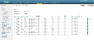
After you have specified the ACL you need to take it into use by first selecting Access Control Lists from the side bar and by choosing your ACL and specifying the CPU ACL Mode to Wired or Both.
Access Point configuration
If the access points are connected to the same subnet as the controller, they will automatically find the controller and connect to it. If this is not the case, the IP address of the controller must be find from the name server by the name CISCO-LWAPP-CONTROLLER. Once the access point has found the controller, it stores the IP of the controller, and it can connect to it from any network, as long as the network allowed access in the ACL (see previous section).
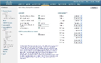
The next step is to define the wireless network, which has to be done separately for 2,4 GHz and 5 GHz. First, choose WIRELESS and then 802.11b/g/n | Network. Enabling the 802.11b-standard will result in less available capacity on your network and therefore it is recommended to enable only the standards 802.11g and 802.11n. Enable 802.11g according to the figure shown below. If you want to support also the 802.11-b standard, set _Mandatory for 1 Mbps and _Supported_ for all other data rates.
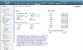
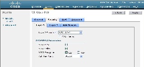
Next, switch to enable the standard 802.11a for 5 GHz by selecting 802.11a/n | Network. Configure the settings according to the figure below.
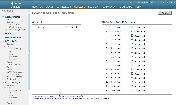
The only standard left to enable is the standard 802.11n. You can choose to enable it for either 2,4 GHz or 5 GHz. It has been suggested that 802.11n is enabled only on the 5 GHz band, in order to utilise the radio resources effectively, see the Campus Best Practice document on "WLAN network planning and setup" Chapter 6.3. http://www.terena.org/activities/campus-bp/pdf/gn3-na3-t4-wlan-network-planning.pdf. To enable 802.11n in the network select 802.11a/n | High throughput (802.11n) and/or 802.11b/g/n | High throughput (802.11n) and configure the settings according to the figure below.
At this point you have enabled the radios, but you have not yet defined any network, so don't try to use the access points just yet.
Defining the RADIUS server
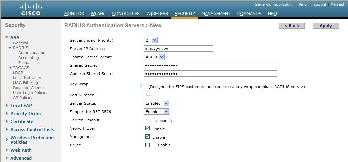
Define the RADIUS server to be used in the eduroam network by selecting SECURITY and then AAA | RADIUS | Authentication. Define the IP address, the shared secret and the other parameters according to figure. Please note that your first server will naturally have a server index of one.
Defining a wireless network
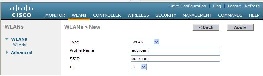
Select WLANs and then WLANs | WLANs from the sidebar. Create a new network and name it as shown in the figure below.
After defining the eduroam network, click on the WLAN ID number to start defining the settings for the network. Set the General settings according to the figure below, then click the Security tab.

In order to enable only WPA2-AES, fill in the security settings as shown in the figure below.
After this, click on the AAA Servers tab and select the RADIUS server that you defined earlier to be used in eduroam.

Next, click on the QoS tab and make sure that you have set the WMM Policy to either Required or Allowed. Otherwise, the higher transmission rates associated with the 802.11n-standard will not work. Then select the Advanced tab and adjust the settings as shown in the figure below. By choosing the parameter P2P Blocking Action to have the value Forward-UpStream, you can prevent WLAN clients to communicate directly, without involving the AP, as recommended in the Campus Best Practice document on "WLAN Information Security" Chapter 2.2 and 2.3. MFP Client Protection is known to have caused problems and can be disabled.

At this stage, click Apply. In the Advanced-tab, the Client Exclusion timeout value was set to 60s. While this is a suitable value, the rules for client exclusion are a bit too strict. Hence, it pays off to adjust the rules by selecting SECURITY and then Wireless Protection Policies | Client Exclusion Policies from the sidebar and uncheck all other options except for "IP Theft or IP Reuse".
These are the basic settings for the Cisco controller. More advanced settings can be found from the upcoming Campus Best Practice document on "WLAN infrastructure", to be published in the first half of 2011.
<to be continued>